
Occasionally, an industrial manager will be faced with a manufacturing problem involving the quality or conformity to standards of a product. In this situation, he or she may think that the matter could be addressed by using machine vision to inspect the product at some point along the line. A short investigation into implementing machine vision will show that this is a complex undertaking. Machine vision is a complex technology, having many factors that bear on the degree of success in its application.
Like most complex matters, machine vision is best tackled by first breaking it down into conceptually distinct elements. This analysis is represented by the block diagram below.
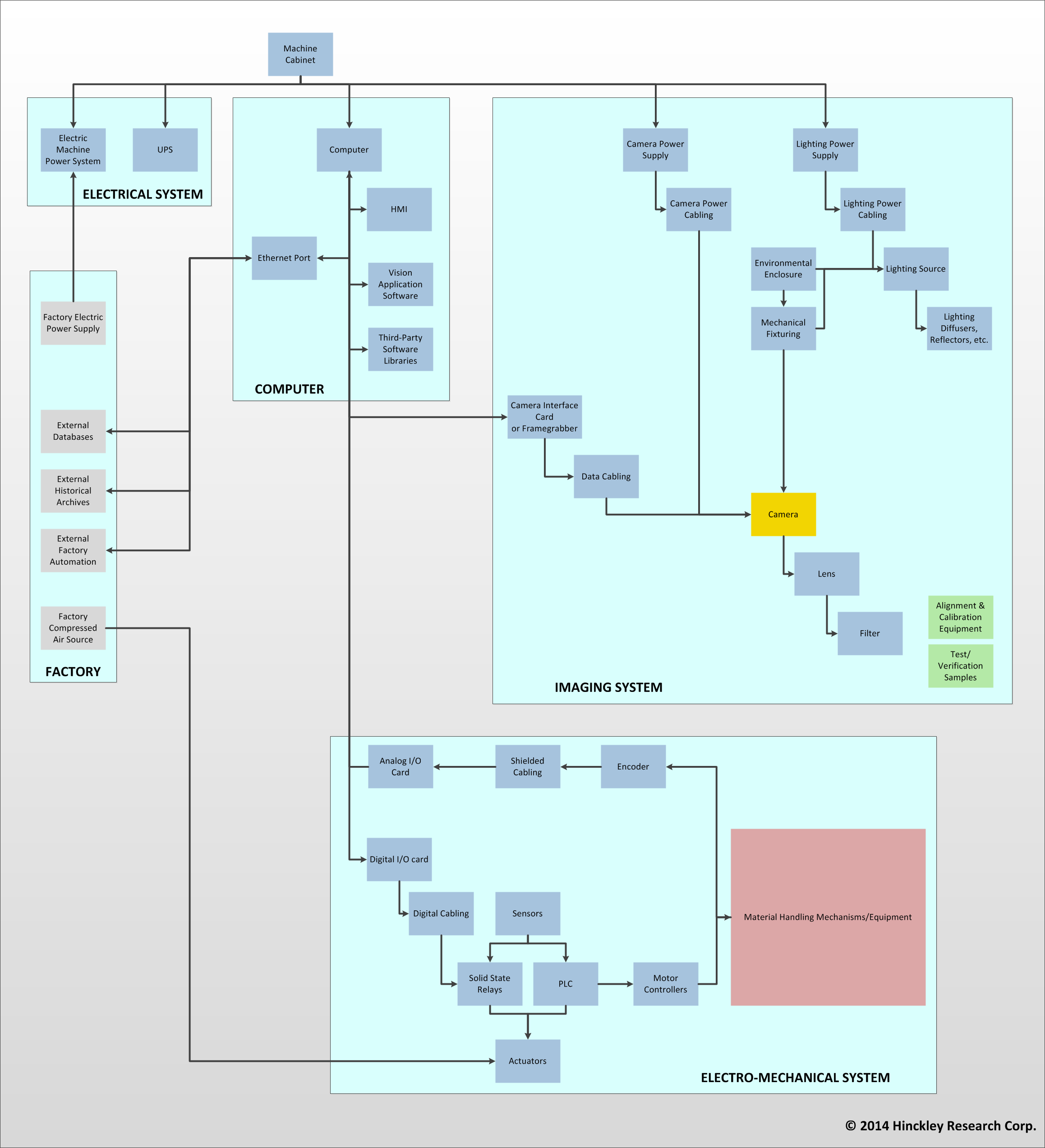
This diagram represents a generic machine vision system. In addition to the imaging system, centered about the camera and illumination, are the electro-mechanical system, encompassing the material handling equipment, the computer, controlling the vision machine, and the electrical power system. Vision machines do not operate in a vacuum and various elements of the factory usually bear on the machine, as well.
Often, when people think of applying machine vision, they think principally about the camera. But, as can be seen in the diagram, the camera, represented in yellow, is but one part of a complex machine. In my experience, from the standpoint of successful implementation, the most critical part of a machine vision system, is not the camera or other part of the imaging system. It is the material handling system. This is why this element is drawn to stand out in the diagram, as a large red rectangle.
When we wish to assess the feasibility of using machine vision, we must remember that the machine (usually) cannot pick up the part under inspection and turn it about, getting multiple views, the way that we can when hold it in our hands and view it with our eyes. Usually, the vision machine gets one single chance to view the part under inspection. Generally speaking, we engineers must carefully configure the geometrical relationship between the camera, illumination source and part so that the feature of interest is reliably visible to the imaging system. Think, for example, of how you need to view a part from a particular low angle in order see a scratch on its surface.
On the production line, it is the job of the material handling system to present each part in a manner that is sufficiently consistent for the imaging system to be able to detect the feature of interest. For most parts, this is a surprisingly difficult task to engineer. Some examples from my experience are as follows:
- Molded rubber parts. These are sticky and non-rigid. Therefore, they tend to clump together and get “hung-up” in the feeding system.
- Cherries and apple slices. These are processed in great volumes and it is necessary to feed them in a manner that spreads them out.
- Sizing of chips in cast metal parts. Here the part, which usually has a complex shape, must be mechanically gripped in a manner that presents it consistently to the camera, so that chip size can be determined without having to infer perspective effects.
- Light-weight plastic pharmaceutical capsules. These tend to pick up a static charge in their mechanical handling. This makes them jump around in the vision machine and not to reliably follow the feeding mechanism.
- Plastic food cups. These are produced and conveyed at a great rate. They have a flange where the foil lid is sealed to the cup body. Because of the shape of the cup, they tend to “shingle” where the flange of one cup overlays that of the next cup in the line. If you are trying to inspect this flange area, this shingling behavior must be prevented.
- Large machine assemblies. Here, the objective may be to inspect a relatively small feature on a large mechanical assembly. If the conveying system doesn’t bring each assembly to a consistent stopped position, you will encounter variation in the appearance of the small feature of interest.
- Large area stamped parts with small features. Here, the part is imaged as it is being conveyed, using a linescan camera for imaging. It is necessary that the part be moved smoothly, especially as it transitions a gap through which back-light illumination is provided. Also, variation in conveyor speed must be measured so that the linescan rate can be controlled to match, avoiding image distortion.
Two generally desirable features of material handling systems, namely high throughput rate and versatility to handle a range of parts, tend to be at odds with the necessary ability of the handling system to present the parts in a consistent manner which is amenable to detecting the features of interest with the camera. In my opinion, the engineering of a material handling system which meets these conflicting objectives to a satisfactory degree, is the most critical element in the success of a machine vision system, in the general case.
However, life of the machine vision engineer is still more challenging. In at least half of the systems that I have worked on, the vision function must be integrated into an existing line. In this situation, you have a substantially lessened opportunity to specify the means of handling and guiding the part or product to be inspected. It may even be a challenge to get a clear, illuminated view of the product, let alone, to say anything about how it is to be moved! Sometimes, stabilization devices can be added to an existing line to constrain the part to within a smaller range of variation. However, there is a limit to how far you can go here, without negatively impacting the rate of throughput.
Bearing these factors in mind, my general approach to determining the feasibility of implementing a machine vision system, is the following.
1. Visit the plant.
- Take note of any relevant environmental factors, such as heavy vibration such as from a stamping press, air-borne contaminants, such as dust or oil mist, water (it’s everywhere in food-processing facilities), light pollution, such as arc welding or bright mercury lights (or sun light, for that matter).
- If the product is to be inspected on an already existing line, determine where along that line, a meaningful view of the product can be obtained, with room for sufficient illumination.
- Examine the behavior of the moving product. Is it moving in a tightly controlled, consistent manner (often it’s not). Are the parts singulated? Do they exhibit other difficult behavior (such as clumping together)?
- What is the current throughput of the line?
- If the proposed vision machine is to be stand-alone, that is it may accept input from a line and provide output back onto the line, but it has its own mechanism for handling the product while imaging, then assess the space available in which to fit the machine.
- What is the anticipated defect rate? This is important, because if your machine will need to reject and remove a large percentage of the product, its sorting efficiency will be diminished.
- What is the natural variation in the appearance and other characteristics of the product?
- Obtain a significant representative sample of the product (spanning the range of characteristics that may vary, such as color and markings) for imaging laboratory analysis. If the proposed machine is to handle a variety of part numbers, samples of each one should be obtained. Both good parts and representative defective parts, ideally showing all of the important type of defects, should be gotten.
- Get a clear and thorough statement from the prospective user of the inspection requirements.
2. Perform an imaging laboratory analysis.
- Bearing in mind the geometrical constraints on available locations of the camera and lights with respect to the product, set up a camera and light source and examine the image obtained of the part.
- The lighting usually has to be carefully designed to exhibit the feature of interest without introducing undesirable artifacts in the image, such as glint.
- Depending on the nature of the features to be examined and the size of the part, the image resolution and the resolving power of the lens will need to be determined.
- The nature of the product’s motion when being inspected and the throughput (number of parts per minute) will determine how fast the system needs to obtain and process the image.
- In testing the imaging, the full range of the product must be considered. This includes the range of positions and orientations that will occur in production, the range of product characteristics, such as color and texture, the range of defects, as represented by your sample (again, be sure to obtain a sample with as wide a range of defects as possible). The objective here is to span all possibilities that will occur on the production line.
- Experiment with image processing methods. You need to find a way of processing the image which reliably shows the feature of interest, under all of the range of variations discussed above.
- This is an iterative process. Generally, you will start with a certain camera, lens and light setup. Take some images and try certain processing methods. This will suggest how the lighting, viewing position and possibly material handling need to be modified to get a more dependable feature detection.
3. Report the results.
- Sometimes you can find a method of meeting all of the requested requirements. Great! Other times, you cannot provide a practical solution that meets everything on the requirements list. In this case, possibly some of the requirements can be dropped or loosened, in the interest of practicality. In other cases, the conclusion is that machine vision is not feasible. Well, this is a feasibility study that you have been doing, and that is always one of the possible outcomes.
- Assuming that the requirements can be met to a satisfactory degree, a cost estimate is required. This requires a degree of care, to be complete. One can see from the above block diagram, that a complete machine vision system has many parts. The specifics of each of these needs to be determined and then appropriate units priced. Along with this, though usually of less significance, is the availability schedule of the components that would be purchased. At this point, a precise quotation is not required, however, you need to know what financial ballpark your machine will be in.